- 您现在的位置:买卖IC网 > Sheet目录2006 > LTC2495CUHF#PBF (Linear Technology)IC ADC 16BIT W/PGA 38-QFN
LTC2495
2495fd
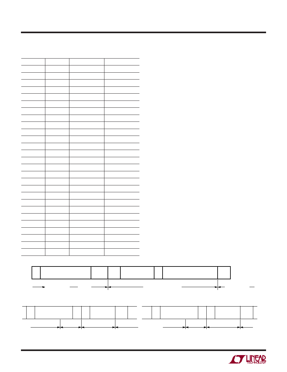
Figure 6. Conversion Sequence
Figure 7. Consecutive Reading with the Same Input/Configuration
Table 6. Address Assignment
CA2
CA1
CA0
ADDRESS
LOW
0010100
LOW
HIGH
0010110
LOW
Float
0010101
LOW
HIGH
LOW
0100110
LOW
HIGH
0110100
LOW
HIGH
Float
0100111
LOW
Float
LOW
0010111
LOW
Float
HIGH
0100101
LOW
Float
0100100
HIGH
LOW
1010110
HIGH
LOW
HIGH
1100100
HIGH
LOW
Float
1010111
HIGH
LOW
1110100
HIGH
1110110
HIGH
Float
1110101
HIGH
Float
LOW
1100101
HIGH
Float
HIGH
1100111
HIGH
Float
1100110
Float
LOW
0110101
Float
LOW
HIGH
0110111
Float
LOW
Float
0110110
Float
HIGH
LOW
1000111
Float
HIGH
1010101
Float
HIGH
Float
1010100
Float
LOW
1000100
Float
HIGH
1000110
Float
1000101
applications inForMation
Operation Sequence
The LTC2495 acts as a transmitter or receiver, as shown
in Figure 6. The device may be programmed to perform
several functions. These include input channel selection,
measure the internal temperature, selecting the line fre-
quency rejection (50Hz, 60Hz, or simultaneous 50Hz and
60Hz), a 2x speed mode and gain.
Continuous Read
Inapplicationswheretheinputchannel/configurationdoes
not need to change for each cycle, the conversion can be
continuously performed and read without a write cycle
(see Figure 7). The configuration/input channel remains
unchanged from the last value written into the device. If
the device has not been written to since power up, the
configuration is set to the default value. At the end of a
read operation, a new conversion automatically begins.
At the conclusion of the conversion cycle, the next result
may be read using the method described above. If the
conversion cycle is not concluded and a valid address
selects the device, the LTC2495 generates a NACK signal
indicating the conversion cycle is in progress.
Continuous Read/Write
Once the conversion cycle is concluded, the LTC2495
can be written to and then read from using the repeated
START (Sr) command.
Figure 8 shows a cycle which begins with a data write, a
repeated START, followed by a read and concluded with a
STOP command. The following conversion begins after all
S
ACK
DATA
Sr
DATA TRANSFERRING
P
SLEEP
DATA INPUT/OUTPUT
CONVERSION
7-BIT ADDRESS
R/W
2495 F05
7-BIT ADDRESS
CONVERSION
SLEEP
DATA OUTPUT
7-BIT ADDRESS
S
R
ACK
READ
P
2495 F07
发布紧急采购,3分钟左右您将得到回复。
相关PDF资料
LTC2496IUHF#TRPBF
IC ADC 16BIT DELTA SIG 38-QFN
LTC2498IUHF#TRPBF
IC ADC 24BIT 16CH 38-QFN
LTC2600IUFD#PBF
IC DAC OCTAL R-R 16BIT 20-QFN
LTC2602IMS8#TRPBF
IC DAC 16BIT DUAL R-R VOUT 8MSOP
LTC2604IGN-1#TRPBF
IC DAC 16BIT QUAD R-R OUT 16SSOP
LTC2605IGN-1#TRPBF
IC DAC 16BIT OCT I2C 16-SSOP
LTC2606IDD#TRPBF
IC DAC 16BIT I2C V-OUT 10-DFN
LTC2607IDE#TRPBF
IC DAC 16BIT R-R I2C 12-DFN
相关代理商/技术参数
LTC2495CUHF#TRPBF
功能描述:IC ADC 16BIT W/PGA 38-QFN RoHS:是 类别:集成电路 (IC) >> 数据采集 - 模数转换器 系列:- 标准包装:2,500 系列:- 位数:16 采样率(每秒):15 数据接口:MICROWIRE?,串行,SPI? 转换器数目:1 功率耗散(最大):480µW 电压电源:单电源 工作温度:-40°C ~ 85°C 安装类型:表面贴装 封装/外壳:38-WFQFN 裸露焊盘 供应商设备封装:38-QFN(5x7) 包装:带卷 (TR) 输入数目和类型:16 个单端,双极;8 个差分,双极 配用:DC1011A-C-ND - BOARD DELTA SIGMA ADC LTC2494
LTC2495IUHF#PBF
功能描述:IC ADC 16BIT W/PGA 38-QFN RoHS:是 类别:集成电路 (IC) >> 数据采集 - 模数转换器 系列:- 标准包装:1 系列:microPOWER™ 位数:8 采样率(每秒):1M 数据接口:串行,SPI? 转换器数目:1 功率耗散(最大):- 电压电源:模拟和数字 工作温度:-40°C ~ 125°C 安装类型:表面贴装 封装/外壳:24-VFQFN 裸露焊盘 供应商设备封装:24-VQFN 裸露焊盘(4x4) 包装:Digi-Reel® 输入数目和类型:8 个单端,单极 产品目录页面:892 (CN2011-ZH PDF) 其它名称:296-25851-6
LTC2495IUHF#TRPBF
功能描述:IC ADC 16BIT W/PGA 38-QFN RoHS:是 类别:集成电路 (IC) >> 数据采集 - 模数转换器 系列:- 标准包装:1,000 系列:- 位数:16 采样率(每秒):45k 数据接口:串行 转换器数目:2 功率耗散(最大):315mW 电压电源:模拟和数字 工作温度:0°C ~ 70°C 安装类型:表面贴装 封装/外壳:28-SOIC(0.295",7.50mm 宽) 供应商设备封装:28-SOIC W 包装:带卷 (TR) 输入数目和类型:2 个单端,单极
LTC2496CUHF#PBF
功能描述:IC ADC 16BIT DELTA SIG 38-QFN RoHS:是 类别:集成电路 (IC) >> 数据采集 - 模数转换器 系列:- 标准包装:1 系列:microPOWER™ 位数:8 采样率(每秒):1M 数据接口:串行,SPI? 转换器数目:1 功率耗散(最大):- 电压电源:模拟和数字 工作温度:-40°C ~ 125°C 安装类型:表面贴装 封装/外壳:24-VFQFN 裸露焊盘 供应商设备封装:24-VQFN 裸露焊盘(4x4) 包装:Digi-Reel® 输入数目和类型:8 个单端,单极 产品目录页面:892 (CN2011-ZH PDF) 其它名称:296-25851-6
LTC2496CUHF#TRPBF
功能描述:IC ADC 16BIT DELTA SIG 38-QFN RoHS:是 类别:集成电路 (IC) >> 数据采集 - 模数转换器 系列:- 标准包装:2,500 系列:- 位数:16 采样率(每秒):15 数据接口:MICROWIRE?,串行,SPI? 转换器数目:1 功率耗散(最大):480µW 电压电源:单电源 工作温度:-40°C ~ 85°C 安装类型:表面贴装 封装/外壳:38-WFQFN 裸露焊盘 供应商设备封装:38-QFN(5x7) 包装:带卷 (TR) 输入数目和类型:16 个单端,双极;8 个差分,双极 配用:DC1011A-C-ND - BOARD DELTA SIGMA ADC LTC2494
LTC2496IUHF#PBF
功能描述:IC ADC 16BIT DELTA SIG 38-QFN RoHS:是 类别:集成电路 (IC) >> 数据采集 - 模数转换器 系列:- 标准包装:2,500 系列:- 位数:16 采样率(每秒):15 数据接口:MICROWIRE?,串行,SPI? 转换器数目:1 功率耗散(最大):480µW 电压电源:单电源 工作温度:-40°C ~ 85°C 安装类型:表面贴装 封装/外壳:38-WFQFN 裸露焊盘 供应商设备封装:38-QFN(5x7) 包装:带卷 (TR) 输入数目和类型:16 个单端,双极;8 个差分,双极 配用:DC1011A-C-ND - BOARD DELTA SIGMA ADC LTC2494
LTC2496IUHF#TRPBF
功能描述:IC ADC 16BIT DELTA SIG 38-QFN RoHS:是 类别:集成电路 (IC) >> 数据采集 - 模数转换器 系列:- 标准包装:2,500 系列:- 位数:16 采样率(每秒):15 数据接口:MICROWIRE?,串行,SPI? 转换器数目:1 功率耗散(最大):480µW 电压电源:单电源 工作温度:-40°C ~ 85°C 安装类型:表面贴装 封装/外壳:38-WFQFN 裸露焊盘 供应商设备封装:38-QFN(5x7) 包装:带卷 (TR) 输入数目和类型:16 个单端,双极;8 个差分,双极 配用:DC1011A-C-ND - BOARD DELTA SIGMA ADC LTC2494
LTC2497CUHF#PBF
功能描述:IC ADC 16BIT W/PGA 38-QFN RoHS:是 类别:集成电路 (IC) >> 数据采集 - 模数转换器 系列:- 标准包装:1 系列:microPOWER™ 位数:8 采样率(每秒):1M 数据接口:串行,SPI? 转换器数目:1 功率耗散(最大):- 电压电源:模拟和数字 工作温度:-40°C ~ 125°C 安装类型:表面贴装 封装/外壳:24-VFQFN 裸露焊盘 供应商设备封装:24-VQFN 裸露焊盘(4x4) 包装:Digi-Reel® 输入数目和类型:8 个单端,单极 产品目录页面:892 (CN2011-ZH PDF) 其它名称:296-25851-6